

Carbon Capture and Storage
What is Carbon Capture and Storage? How does it work ? How expensive is it?

Carbon Capture and Storage or ‘CCS’ often appears as a solution to mitigate CO2 emissions and reach carbon targets. But what is this technology ? In this article, we explore what CCS is and analyze its various stages.
What is CCS?
Carbon Capture and Storage (CCS) typically involves three key stages: carbon capture, transport, and storage. In the capture stage, an industrial facility separates carbon dioxide (CO₂) emissions from the rest of the flue gas. These captured emissions are then transported to a storage site, where the CO₂ is injected into geological underground formations. Because of this process, CCS is often presented as a CO₂ mitigation technology and plays an important role in decarbonization scenarios, as highlighted in recent reports from the IPCC and the IEA.
While this formal definition is instructive, it doesn’t fully reflect the diversity of technologies that fall under the CCS umbrella as illustrated in Figure 1 below. Let’s break these technologies down with a brief historical perspective.
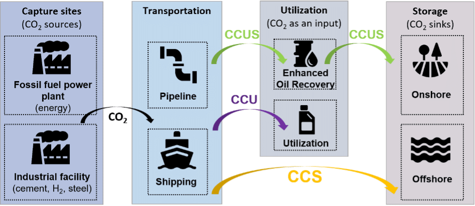
Figure 1: Schematic representation of various CC(U)S schemes. Authors’ elaboration.
In the early 1970s in the United States, the first integrated projects combining CO2 capture, transport, and underground storage began to emerge. At the time, the goal wasn’t to reduce emissions, but to inject CO2 into oil fields to boost extraction. This process is known as CO2 flooding and falls within a broader suite of techniques aimed at extracting more oil, collectively known as Enhanced Oil Recovery (EOR, or sometimes CCS-EOR).
The idea of capturing, transporting, and storing CO2 specifically to reduce atmospheric emissions only gained prominence in the late 1990s (von Hirschhausen et al., 2012).[1] CCS was soon promoted as a climate mitigation tool for emissions from coal-fired power plants and a wide range of industrial sectors – including cement, steel, pulp and paper, refining, and petrochemicals.
Alternative approaches began to emerge: instead of treating CO₂ solely as a waste to be stored, some proposed using it as a resource, leading to what is known as Carbon Capture and Utilization (CCU). For example, using CO₂ to synthesize methanol is considered a CCU process. If CO₂ is both used in an industrial application and ultimately stored underground rather than ending up in a product, the process is often referred to as Carbon Capture, Utilization, and Storage (CCUS). Because CO₂ is both utilized and stored underground in Enhanced Oil Recovery, EOR is typically classified under CCUS.
Two final strands of technology related to CCS are also worth mentioning: Bioenergy with Carbon Capture and Storage (BECCS), which involves capturing CO₂ from biomass-based energy production, and Direct Air Capture (DAC), which captures CO₂ directly from ambient air. These approaches are particularly relevant in discussions about “negative emissions” technologies. These two strands of technologies are often regrouped under the acronym CDR for Carbon Dioxide Removal technologies.
It’s important to note that these definitions aren’t universal or set in stone. Depending on the report, authors may include or exclude certain technologies from the CCS category. For instance, recent IPCC reports treat CCS, BECCS, and DAC as distinct categories, while the IEA tends to group them all under the broader umbrella of CCUS technologies.
In the following subsections, we describe the main characteristics of carbon capture, transport and storage.
What is carbon capture?
The capture stage does not apply to any type of CO2 emitter: it is generally done at an industrial site, whose CO2 emissions are separated from the rest of the flue gas emitted during production. In this context, capturing CO2 emissions simply means separating it from the rest of the gas emitted into the atmosphere. Hence, the capture equipment can be added to an existing plant without modifying its functioning. When this is the case, the capture site is defined as being retrofitted, acknowledging that the capture equipment was added after initial planning. In terms of decarbonization perspectives, this feature means that most industrial units can be retrofitted in place, which is a great advantage for large-scale deployment.
Naturally, capturing CO2 emissions comes at the expense of higher energy consumption. Moreover, an industrial site whose production process initially integrates CO2 capture is expected to be more energy-efficient than a similar one that has been retrofitted. The energy increase required to fuel the capture equipment is far from negligible: the so-called energy penalty can represent an increase between 5 and 40% of the energy input (Wang et al. 2022; Gustafsson et al. 2021). This large range varies depending on the industrial process under consideration (coal power plant, cement production, BECCS…) and the type of capture technology.
Indeed there are multiple capture technologies. Capture technologies are often grouped by where in the combustion process CO₂ is removed, typically before combustion (pre-combustion), after combustion (post-combustion), or by using pure oxygen to simplify CO₂ separation (oxy-fuel combustion), see Figure 2 below. Other innovative approaches, like chemical looping absorption, are also being explored. Instead of classifying capture processes by where they intervene in the industrial process, some reports choose to classify them by the mechanisms they use to separate CO2 (such as adsorption, physical absorption, membrane, looping cycles). We discuss the technology readiness levels of various capture separation mechanisms in the next subsection. We do not detail the actual physical process behind these capture separation mechanisms, but it is useful to know that multiple approaches exist, each suited to different industrial contexts.
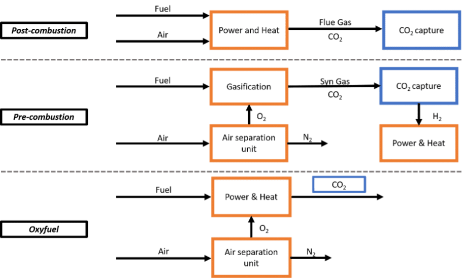
Figure 2 : Visual representation of usual capture technology processes. Based on Dubey et Arora (2022).
How much does carbon capture cost?
The short answer would be: it depends on which cost we’re talking about.
Indeed, there is no general consensus to what “carbon capture cost” refers to, which can lead to confusion. Broadly, there are two main definitions for it:
- the cost of CO2 captured
- the cost of CO2 avoided
These metrics differ significantly. As shown in the figure below, the cost of CO2 avoided is higher. For policymakers, CO₂ avoidance cost is typically the more relevant metric, since it reflects the actual net reduction in emissions.
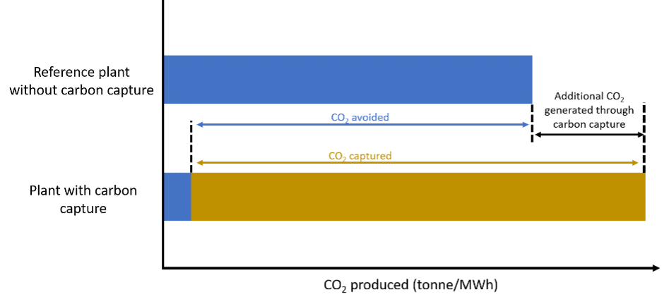
Figure 3: CO2 capture cost versus CO2 avoidance cost. Adapted from Wilberforce et al. (2021).
What drives the cost of capture?
Several key factors determine how expensive capture is:
- The capture technology: Different technologies are better suited to different industrial processes. In the cement sector, some studies find an avoidance cost of around 40€/tCO2, avoided with oxyfuel technology and 80€/tCO2, avoided for the monoethanolamine-based (MEA) process (Gardarsdottir et al. 2019; Roussanaly et al. 2021). While oxyfuel might seem like the best fit, it is technologically less mature than the MEA process and its cost depends strongly on the cement plant under consideration (Voldsund et al. 2019).
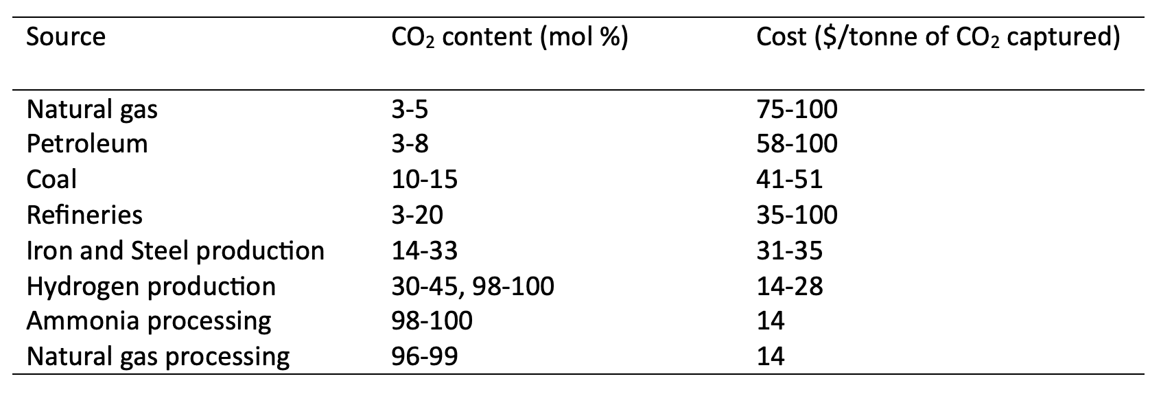
- The concentration of CO2 in the flue gas: Capture becomes easier (and cheaper) when CO₂ is more concentrated. According to the Sherwood-analysis conducted by Bains et al. (2017), low CO₂ concentrations sharply increase the energy and cost required for separation. A summary of capture costs at various CO₂ concentrations is shown in the Table 1
Table 1: Estimates for cost of CO2 captured for top CO2 emitting industries in the US (Bains, Psarras, et Wilcox 2017)
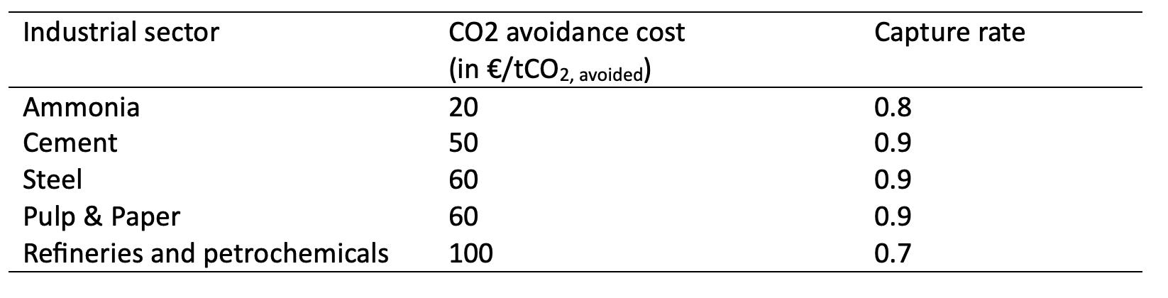
- The capture rate: Achieving higher capture rates increases energy consumption. Each marginal CO₂ captured costs more than the previous one. In this perspective, it is crucial to always specify the assumed capture rate when citing capture costs. Table 2 below presents capture cost estimates across different industries and capture rates. While this offers a general comparison, it’s important to note that cost ranges are typically more informative. For a more accurate view, see resources such as the IEA – Levelized Cost of Capture
Table 2: General overview of carbon capture avoidance cost for various industrial sectors. Authors’ compilation based on (Roussanaly et al. 2021; Gardarsdottir et al. 2019; Garcia et Berghout 2019; Biermann et al. 2019; Voldsund et al. 2019; Bains, Psarras, et Wilcox 2017; Leeson et al. 2017)
Beyond the core technical factors, many other parameters influence the cost of carbon capture at an industrial site. For example, site-specific conditions such as access to raw materials, electricity prices, existing infrastructure, and local expertise can significantly affect total costs.
How do we assess the maturity of capture technologies?
According to a recent report by the Joint Research Centre (Joint Research Centre et al. 2024) the various components of carbon capture span different levels on the Technology Readiness Level (TRL) scale. This scale ranges from TRL 1 (concept stage) to TRL 9 (commercial deployment), and is commonly used to assess the maturity of technological innovations. For CCS to be deployed at scale, it is generally understood that each stage (capture, transport, and storage) must reach TRL 9.
Regarding capture, the report finds that multiple standalone technologies have reached a TRL 9.[2] However, this does not prove that the capture stage is mature across all contexts. Indeed, the report also maps the TRL when integrated into a specific industrial process. They obtain the following Figure 4:
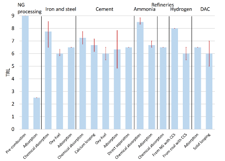
Figure 4: Average TRL of CO2 capture technologies and sub-technologies (red vertical ranges represent maximum and minimum levels reported). Source: Joint Research Centre (2024).
The figure above reveals that only natural gas processing has capture technologies at commercial scale (i.e., TRL 9), followed by ammonia and hydrogen production (with TRLs of around 8). Note that the figure does not cover capture technologies at power plants, which is generally considered as a mature technology with TRL 9 (Bui et al. 2018).
How is CO2 transported?
Following the capture stage, CO₂ is transported to its storage site. Pipeline transport is generally the first option considered, due to its strong economies of scale and low unit cost per tonne transported.
When transported via pipeline, CO₂ can be in gaseous, supercritical, or dense (subcooled liquid) form. In the dense phase, the fluid is compressed above its supercritical pressure (typically >73.8 bar), but kept below the supercritical temperature (31.1°C), making it easier to handle. Both supercritical and dense-phase CO₂ offer cost advantages over gaseous CO₂ due to their higher density, allowing narrower pipelines and lower pressure drops (Zhang et al. 2006; Knoope et al. 2014).
That said, repurposing existing natural gas pipelines may favor gaseous CO₂ transport. In such cases, it may be more cost-effective to reuse existing infrastructure (including compressor stations) rather than install a new pipeline with pumping infrastructure for liquid-phase transport. For example, a study on pipeline repurposing in Scotland found that below a threshold of 10 MtCO₂/year, transporting CO₂ in gaseous form via a repurposed pipeline is more economical than building a new liquid-phase pipeline (Brownsort, Scott, et Haszeldine 2016). Eventually, adding new compressor stations can boost the volumes being transported below this threshold.
Beyond pipelines, various transportation modes are available: trucks, trains, barges, or ships. These can be either container-based or dedicated. Container-based systems involve loading CO₂ into transportable containers, offering the advantage of minimal infrastructure investment, which enables faster deployment and greater flexibility. Dedicated options (e.g., purpose-built trains or ships), while requiring more upfront investment, typically offer lower costs per tonne and stronger economies of scale. A qualitative comparison of the main transport options is provided in Table 3.
Table 3: Multi-criteria assessment of selected CO2 transportation modes. Characteristics are qualitatively ranked from best to worse following : ++, +, 0, -, –. Based on Oeuvray et al. (2024).
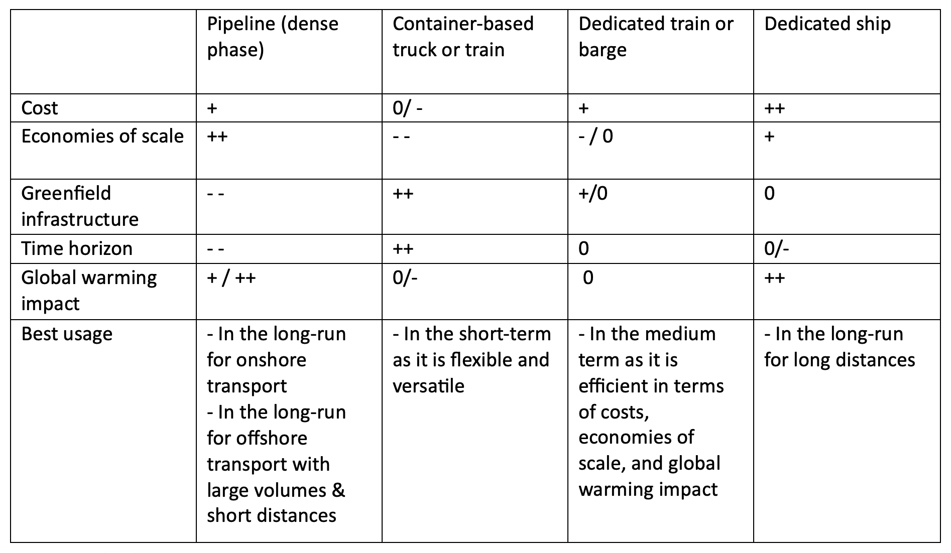
In the long-run, pipelines and dedicated ships are considered the most viable solutions due to their cost-efficiency and scalability. However, because they involve substantial sunk costs, container-based or modular transport options may be more attractive for early-stage projects.
How much does CO2 transport cost ?
Due to strong economies of scale, the unit cost of CO₂ transport via pipelines and dedicated ships typically decreases as the transported volume increases – a behavior represented by convex cost functions with respect to flowrate. This is illustrated in the figure 5 below. Note that these values are case-specific and would need to be adapted for other regions.
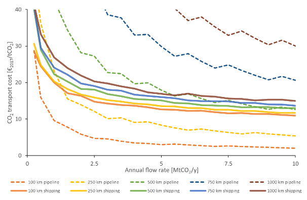
Figure 5: Unitary transport cost via shipping or pipeline in function of the annual transported CO2 flowrate for different transport distances (Roussanaly et al. 2021)
In contrast, the unitary cost of container-based transport modes (such as truck, train, or barge) tend to be less sensitive to flowrate, but are instead inversely related to transport distance (Oeuvray et al. 2024).
How does CO2 storage work?
Once it reaches the storage site, CO₂ must be stored in a deep geological reservoir, see Figure 6 below. A common misconception is that CO₂ is stored as a gas, whereas it is actually stored as a supercritical fluid — a dense phase with properties of both gas and liquid. The two main types of geological formations used for CO₂ storage are saline aquifers and depleted oil and gas fields.
- Deep saline aquifers: These consist of porous and permeable rock formations saturated with saline water. They are typically located at depths of 800 to 3000 meters, well below drinking water sources (Celia et al. 2015). In deep saline aquifers, several complementary mechanisms work together to ensure CO₂ is securely stored over time (Bashir et al. 2024). Initially, static trapping prevents CO₂ from migrating upward, as it accumulates beneath impermeable rock layers (caprock) due to buoyancy forces. As CO₂ moves through the reservoir, capillary trapping immobilizes small amounts of it in rock pores via surface tension, disconnecting it from the main plume. Over longer timescales, solubility trapping occurs as CO₂ dissolves into the surrounding brine, forming a denser fluid that sinks and becomes more stable. Finally, mineral trapping gradually converts dissolved CO₂ into solid carbonate minerals through geochemical reactions with the rock matrix, providing permanent immobilization. One of the first large-scale CO₂ storage projects using saline aquifers was the Sleipner project in the North Sea, where CO₂ has been injected into the Utsira Sandstone Formation since 1996. The TRL for CO₂ storage in deep saline aquifers is estimated at 9.
- Storage in depleted oil & gas field: Depleted oil and gas reservoirs are geological formations where hydrocarbons have been previously extracted. These sites are often well-characterized, with extensive geological data available (seismic surveys, well logs, core samples, etc…) offering detailed insight into rock properties such as porosity, permeability, and caprock integrity. Because they have successfully trapped oil and gas for millions of years, they are considered reliable candidates for long-term CO₂ storage (Agartan et al. 2018). In addition to their proven sealing capacity, these reservoirs often benefit from existing infrastructure and operational experience, especially where enhanced oil recovery (EOR) has been used. Several trapping mechanisms work in combination, mainly static and capillary trapping. Given the maturity of these systems, the TRL of storage in depleted oil and gas fields is also at 9.
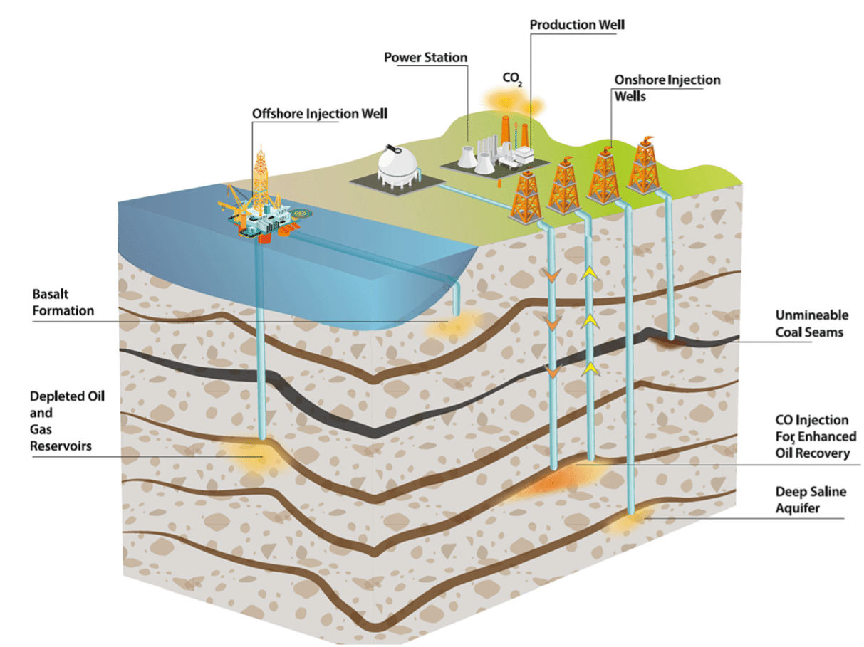
Figure 6: CO2 geological storage options (Bashir et al. 2024).
Overall, effective CO₂ storage relies on several key criteria: sufficient depth, chemical reactivity of the reservoir, and the trapping mechanisms involved. Storage at depths typically greater than 800 meters ensures that CO₂ remains in a dense, supercritical state, maximizing storage efficiency and minimizing leakage risk. The chemical interactions between CO₂, formation brine, and rock contribute to long-term stabilization. Yet, a detailed geological understanding of the storage site, including its structure, caprock integrity, and fluid dynamics, is essential for safe and predictable containment. Together, these factors form the foundation of secure, durable geological CO₂ storage.
How much does CO2 storage cost?
Studies indicate that costs differ by reservoir type, with offshore storage typically more expensive than onshore options (Rubin et al., 2015). The flow rate (i.e., the volume of CO₂ injected) also significantly influences the cost per tonne. While storage costs are often cited around €10/tCO₂, this average value masks a wide range of possibilities. When combined with transportation costs, Smith et al. (2021) report a total cost ranging from €4/tCO₂ to €45/tCO₂. This broad range reflects key sources of variability, including transport distance, project scale, monitoring requirements, reservoir geology, and infrastructure costs such as injection wells capital investment. The figure below is indicative of storage costs.
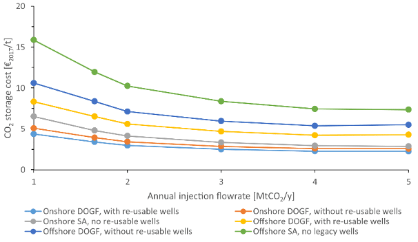
Figure 7: Storage cost of various storing solutions (DOGF: Depleted Oil and Gas Field, SA: Saline Aquifer). Figure by (Roussanaly et al. 2021).
Do you want to know more?
If you want to know more about this topic and get in touch with the FSR Molecules and Materials team, please contact Chiara Canestrini.
This Cover the Basics benefited from the contribution of Adrien Nicolle.
References
Agartan, Elif, Manohar Gaddipati, Yeung Yip, Bill Savage, et Chet Ozgen. 2018. « CO2 Storage in Depleted Oil and Gas Fields in the Gulf of Mexico ». International Journal of Greenhouse Gas Control 72 (mai):38‑48. https://doi.org/10.1016/j.ijggc.2018.02.022.
Bains, Praveen, Peter Psarras, et Jennifer Wilcox. 2017. « CO2 Capture from the Industry Sector ». Progress in Energy and Combustion Science 63 (novembre):146‑72. https://doi.org/10.1016/j.pecs.2017.07.001.
Bashir, Ahmed, Muhammad Ali, Shirish Patil, Murtada Saleh Aljawad, Mohamed Mahmoud, Dhafer Al-Shehri, Hussein Hoteit, et Muhammad Shahzad Kamal. 2024. « Comprehensive Review of CO2 Geological Storage: Exploring Principles, Mechanisms, and Prospects ». Earth-Science Reviews 249 (février):104672. https://doi.org/10.1016/j.earscirev.2023.104672.
Brownsort, Peter A., Vivian Scott, et R. Stuart Haszeldine. 2016. « Reducing Costs of Carbon Capture and Storage by Shared Reuse of Existing Pipeline—Case Study of a CO 2 Capture Cluster for Industry and Power in Scotland ». International Journal of Greenhouse Gas Control 52 (septembre):130‑38. https://doi.org/10.1016/j.ijggc.2016.06.004.
Bui, Mai, Claire S. Adjiman, André Bardow, Edward J. Anthony, Andy Boston, Solomon Brown, Paul S. Fennell, et al. 2018. « Carbon Capture and Storage (CCS): The Way Forward ». Energy & Environmental Science 11 (5): 1062‑1176. https://doi.org/10.1039/C7EE02342A.
Celia, M. A., S. Bachu, J. M. Nordbotten, et K. W. Bandilla. 2015. « Status of CO2 Storage in Deep Saline Aquifers with Emphasis on Modeling Approaches and Practical Simulations: STATUS OF CO2 STORAGE IN DEEP SALINE AQUIFERS ». Water Resources Research 51 (9): 6846‑92. https://doi.org/10.1002/2015WR017609.
Dubey, Aseem, et Akhilesh Arora. 2022. « Advancements in Carbon Capture Technologies: A Review ». Journal of Cleaner Production 373 (novembre):133932. https://doi.org/10.1016/j.jclepro.2022.133932.
Gardarsdottir, Stefania, Edoardo De Lena, Matteo Romano, Simon Roussanaly, Mari Voldsund, José-Francisco Pérez-Calvo, David Berstad, et al. 2019. « Comparison of Technologies for CO2 Capture from Cement Production—Part 2: Cost Analysis ». Energies 12 (3): 542. https://doi.org/10.3390/en12030542.
Gustafsson, Kåre, Ramiar Sadegh-Vaziri, Stefan Grönkvist, Fabian Levihn, et Cecilia Sundberg. 2021. « BECCS with Combined Heat and Power: Assessing the Energy Penalty ». International Journal of Greenhouse Gas Control 108 (juin):103248. https://doi.org/10.1016/j.ijggc.2020.103248.
Joint Research Centre, Martinez Castilla, G, D Tumara, A Mountraki, S Letout, M Jaxa-Rozen, A Schmitz, E Ince, et A Georgakaki. 2024. « Clean Energy Technology Observatory: Carbon Capture Utilisation and Storage in the European Union – 2024 Status Report on Technology Development, Trends, Value Chains and Markets ». Luxembourg: Publications Office of the European Union. https://data.europa.eu/doi/10.2760/0287566.
Knoope, M.M.J., W. Guijt, A. Ramírez, et A.P.C. Faaij. 2014. « Improved Cost Models for Optimizing CO2 Pipeline Configuration for Point-to-Point Pipelines and Simple Networks ». International Journal of Greenhouse Gas Control 22 (mars):25‑46. https://doi.org/10.1016/j.ijggc.2013.12.016.
Oeuvray, Pauline, Johannes Burger, Simon Roussanaly, Marco Mazzotti, et Viola Becattini. 2024. « Multi-Criteria Assessment of Inland and Offshore Carbon Dioxide Transport Options ». Journal of Cleaner Production 443 (mars):140781. https://doi.org/10.1016/j.jclepro.2024.140781.
Roussanaly, Simon, Niels Berghout, Tim Fout, Monica Garcia, Stefania Gardarsdottir, Shareq Mohd Nazir, Andrea Ramirez, et Edward S. Rubin. 2021. « Towards Improved Cost Evaluation of Carbon Capture and Storage from Industry ». International Journal of Greenhouse Gas Control 106 (mars):103263. https://doi.org/10.1016/j.ijggc.2021.103263.
Smith, Erin, Jennifer Morris, Haroon Kheshgi, Gary Teletzke, Howard Herzog, et Sergey Paltsev. 2021. « The Cost of CO2 Transport and Storage in Global Integrated Assessment Modeling ». International Journal of Greenhouse Gas Control 109 (juillet):103367. https://doi.org/10.1016/j.ijggc.2021.103367.
Voldsund, Mari, Stefania Gardarsdottir, Edoardo De Lena, José-Francisco Pérez-Calvo, Armin Jamali, David Berstad, Chao Fu, et al. 2019. « Comparison of Technologies for CO2 Capture from Cement Production—Part 1: Technical Evaluation ». Energies 12 (3): 559. https://doi.org/10.3390/en12030559.
Wang, Yan, Zhen Pan, Wenxiang Zhang, Tohid N. Borhani, Rui Li, et Zhien Zhang. 2022. « Life Cycle Assessment of Combustion-Based Electricity Generation Technologies Integrated with Carbon Capture and Storage: A Review ». Environmental Research 207 (mai):112219. https://doi.org/10.1016/j.envres.2021.112219.
Wilberforce, Tabbi, A.G. Olabi, Enas Taha Sayed, Khaled Elsaid, et Mohammad Ali Abdelkareem. 2021. « Progress in Carbon Capture Technologies ». Science of The Total Environment 761 (mars):143203. https://doi.org/10.1016/j.scitotenv.2020.143203.
Zhang, Z.X., G.X. Wang, P. Massarotto, et V. Rudolph. 2006. « Optimization of Pipeline Transport for CO2 Sequestration ». Energy Conversion and Management 47 (6): 702‑15. https://doi.org/10.1016/j.enconman.2005.06.001.
[1] The concept was however first suggested by Marchetti (1977) in his seminal paper ‘On Geoengineering and the CO2 problem’.
[2] These include : amin absorption, physical absorption solvent, PSA/NSA adsorption and natural gas processing.
Don’t miss any update on this topic
Sign up for free and access the latest publications and insights